
Estimated reading time: 51 minutes
The ultimate guide to SOLIDWORKS Configurations
In this article, we delve into everything configuration-related in SOLIDWORKS. From the basics concepts and use cases for SOLIDWORKS configurations, all the way through to the details of how to design your models and even drawings to account for the configurations.
What are SOLIDWORKS configurations?
SOLIDWORKS configurations allow you to design multiple variations of your model in a single file. This means you can have different sizes and shapes of your model, perhaps with different options and even different materials, all stored as a single item.
When a model with configurations is open in SOLIDWORKS, you can switch between the different versions, and work with them independently. You can check out the mass properties or run an analysis of each configuration separately.
When a model with configurations is used in an assembly, the assembly can decide which configuration to use. If you have multiple instances of a model with configurations in an assembly, each instance can reference a different configuration.
When a drawing displays a model with configurations, each drawing view can choose which configuration of the model is displayed. This allows you to place different versions of your model side-by-side on a single drawing sheet, or to create a single drawing with a sheet for each different model version.
How do SOLIDWORKS configurations work?
Configurations work by storing different values for the parameters in your SOLIDWORKS models. For example, a dimension that is updated to show different sizes of your part.
Imagine something as simple as a washer. By driving the inner diameter, outer diameter, and thickness, you can create a series of different-sized washers.
Example use for SOLIDWORKS configurations
Instead of having a folder full of SOLIDWORKS models for all the different-sized washers, you could have a single part with a configuration for each size. This simplifies your workflow and reduces the files you need to store and maintain. Simply add washer.sldprt, choose the appropriate configuration and you’re done.
Another commonly controlled parameter is the suppression state of a feature. While controlling dimensions alone for a washer would allow us to capture all flat washers and even fender washers, by adding another feature, we could turn our flat washer into an external tooth washer. Another feature could turn a flat washer into an internal tooth washer. You could add features to make any washer from shoulder washers to finishing washers to Belleville washers. And you could use configurations to suppress or unsuppress these features to get the washer you want. This feature suppression also expands to assembly features and mates when you’re working with assembly configurations. Sketches and sketch relation suppression states and even the driving state (driving/driven) of a sketch dimension can all be configuration specific.
Configurations can also control the properties of your model. This allows you to control what shows in annotations on your drawings as well as in Bills of Materials. This could be any custom property (for example finish, vendor, SKU) or it could be special properties that SOLIDWORKS controls like description, part number, material, color, and even whether the configuration is expanded in an indented BOM.
When creating configurations in an assembly, you can control a lot of parameters for each component instance. If that component has configurations, you can have each assembly configuration choose which component configuration it references. Also, you can control the suppression state of each instance and the fixed or floating position of each instance.
There is a large list of more infrequently used parameters that can also be controlled by configurations as well. If you override your mass properties to represent a purchased component, those values can be different for different configurations. If you use scale features, the X, Y, and Z scale factors can be configuration specific. When you are referencing a part with configurations (like inserting it as a component in an assembly) you can choose the part configuration with features like base parts and split parts. And even some feature parameters like end conditions and sketch planes can be different per configuration.
The SOLIDWORKS help file article “Configurable Parameters” is kept updated as new functionality is added to each version of the software. It is always best to check this list when there is a question of what is available to control with configurations.
Example uses of SOLIDWORKS configurations
Now that we understand what configurations are, and what we can control about our models between configurations, let’s look at the most common use cases for why people use configurations.
Same but different products
The most common application for configurations is the creation of families of models. These “same but different” items have a common design to them, with a series of design rules that determine how the product exists. For example, pipe fittings come in a variety of pipe diameters, materials, and angles, some have flanges, and some have internal or external threads…
As we mentioned, we can control dimensions, features, materials, and properties between configurations to make all of these plumbing elbows in a single SOLIDWORKS model.
This means that when we are creating assemblies that utilize these elbows, we can just insert elbow.sldprt and choose which elbow we need. If we decide to create configurations of our assembly, our high-pressure and low-pressure configurations can use the same model instance and use different configurations. The benefits of using configurations in this use case are:
- Fewer files to manage (all elbows are in a single file)
- Easier to configure assemblies (changing the configuration instead of having to use Replace Components or install two separate, competing elbows for each instance)
- The design intelligence is stored once and leveraged to create multiple versions. This means that if the design of the component changes, we only need to update one model, and all versions will be updated.
Representing the state of products
The second most common application for configurations is to represent the different states of a product throughout its lifecycle. Quite often, this refers to the different steps in a manufacturing process. For example, with sheet metal parts, SOLIDWORKS will automatically create bent and flattened configurations through the suppression of features.
Depending upon how many machines are involved in the folding and punching, you might have a series of configurations representing the product at different stages throughout the manufacturing process. Likewise, for a machined part, you can have a configuration representing the part as received from the forge, another configuration representing the model after it comes off the vertical mill, another configuration representing the part after it comes off the drill press, and so on.
In this case, the different configurations are not typically consumed by assemblies, but rather, by drawings. This allows us to create separate 2D drawings for each of our team members in the shop so they can focus strictly on what their particular machining operation requires. This also allows us to create multiple inspection drawings for intermediate inspection stations, so they will have a drawing that accurately represents the part they are receiving. It does also allow us to have a model that we can use to design the tooling and fixturing for the next manufacturing step.
Products that move can also be represented in different states. Something as common as a hinge is often represented with configurations, whether it is being built as a part or an assembly. While a hinge may be composed of three or more parts, to a designer, it’s often a single item that gets ordered with a single part number. This leads to hinges often being built as a single part model, and configurations for open, closed, or 30- and 45-degree angles. Creating an assembly of a hinge and making that assembly flexible so the hinge can be opened and closed often creates an unnecessarily heavy computational load that can slow down your assembly performance.
Moving assemblies are often stored with multiple configurations to show the assembly at its extremes and an intermediate position. This allows the exploration of clearances and mass properties (like the center of mass) in a variety of orientations when used in an even larger assembly. This also allows drawing views to depict the assembly in its various states for assembly, inspection, and maintenance purposes.
Streamlining downstream processes
Configurations are also used to create different representations of models for drawings and other downstream applications that might not depict versions of the model that may not exist in real life. Simplified models are very powerful in drawings to help the reader focus on what is important.
Maintenance manuals can remove components or component details, or could create intricate cutaways that may be difficult or impossible to perform with the drawing view tools. Likewise, it is often beneficial to remove details or features that are not relevant to downstream applications like CAM, or analysis, or export for online viewers.
Removing unnecessary details can enable these products to run more efficiently and create more accurate results. When exporting files for virtual reality or online 3D viewers, for example, it may be necessary to remove details to create a more performant model (with fewer triangles) or to remove intellectual property that should not be made public.
How to create SOLIDWORKS configurations
There are three primary methods for creating configurations in SOLIDWORKS:
- Manual – when you set up configurations manually, you create a new configuration, and then make your changes to configure the product the way that you want it.
- Configuration tables – with the configuration table approach, you determine what about the product you want to configure, then you use a table dialog in SOLIDWORKS to enter the values for each parameter in each configuration. The primary difference between these two approaches is that the manual process is really a configuration-centric approach (you create the configuration, then decide how it will appear) whereas the configuration table process is more parameter-centric (you decide what will change, and then decide how those parameters will be populated for each configuration).
- Design tables – design tables utilize an Excel spreadsheet to populate the parameter values and create the configurations. Like the configuration table method, you are filling in a series of values, but unlike the configuration table method, you do not have to predefine which parameters you want to control. You can add configurations on the fly in the configuration table method one at a time, which you cannot do with the manual method, but design tables strength lies in the ability to import a large amount of data and create many configurations in a single step. The downside to the design table, however, is that there is a syntax involved to the design tables that can be difficult to remember, if not used frequently.
Creating SOLIDWORKS configurations manually
The manual method for creating configurations is used most often when there are a small number of configurations to be created. The process involves going to the Configuration Manager and adding new configurations as they are required. Once a configuration is active, you can change the parameters using the methods that you typically would (for example, double-clicking on a dimension or editing a feature), but you will now see a parameter scope that allows you to choose options like “All Configurations”, “This Configuration” and “Specify Configurations”.
If you change this scope from All Configurations to This Configuration, this parameter then becomes configuration specific, and new values specified will only apply to the currently active configuration.
You can switch between the configurations as you need to, in order to update the parameter values for your model. You can simply capture new parameters as you go. There is no requirement to have all your parameters registered, or even created, in order to start creating configurations.
In addition to the standard model parameters that you are controlling, you can also create configuration-specific custom properties. These are very useful for populating linked annotations, like notes and balloons, in drawings as well as in populating a Bill of Materials (BOM). Configuration-specific custom properties have their own tab in the properties dialog, to separate them from custom properties that apply to all configurations.
Additionally, there are configuration properties in the configuration manager itself that allows you to control the configurations. You can control not only the configuration’s name, but also its description, whether it is used in a Bill of Materials (simplified representations would not be used, for example) and even whether this configuration is excluded from the BOM (as opposed to a different configuration being used), its part number (which can be different from the document name), and even a configuration specific color.
To better support the manual configuration process, there is even an option here that allows you to automatically suppress new features and mates in this configuration. That means that if you add new options to your model, they will automatically be excluded from this version of your product. You can always unsuppress them if that’s not appropriate. This just controls the default behavior.
When you go to create your manual configuration, you can also add a configuration to an existing configuration. This will create a derived configuration, a configuration created from another configuration. Any parameters that drive the parent configuration will automatically drive the child configuration unless they have been explicitly applied to the child.
This allows you to subdivide your product configurations, for example, you could have a model of a washer where you create configurations for the different types of washer (ex. flat, finishing, split) and then under each of those configurations, you could create child configurations for each of the available sizes of each.
This also allows you to mix and match your use cases. We could create configurations for different sizes of sheet metal brackets. Then we could have child configurations for the different manufacturing steps in the bracket’s construction, flat blank, flat punched, ends formed, and fully formed.
Creating SOLIDWORKS configurations with configuration tables
With the manual configuration method, we start by creating and activating a configuration, then we make the changes to that specific configuration. Once you have a series of configurations established, every time that you add a new feature or modify your design intent, then you need to ensure that the changes that you’ve made are reflected correctly in all of your configurations. This could mean setting the dimensional values for each configuration or selecting a feature and determining the suppression state of that feature for each configuration.
SOLIDWORKS anticipates this need and provides an interface to make this easier for you. When you go to suppress or unsuppress a feature in the feature manager by right-selecting it, you will receive the option “Configure Feature…”.
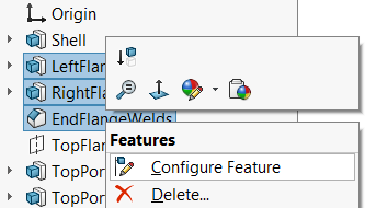
SOLIDWORKS Configure Feature Option
When you select the Configure Feature option, you are presented with the Modify Configurations dialog which allows you to change the selected parameters (feature suppression, in this case) for all the configurations. There is even an option to add a new configuration and a few buttons along the bottom that most people don’t even notice.
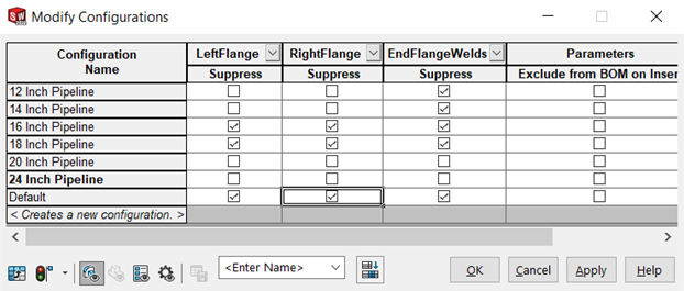
Modify Configurations dialog shown as a table in SOLIDWORKS
The first button just transposes (rotates) the table for easier reading. The rebuild button allows you to control whether just all configurations are rebuilt or just the current configuration. The next section of buttons allows you to show or hide configurable parameters by type (features/sketch dimensions, components, custom properties, configuration parameters). The combo box shows you all of the views of this configuration information that you have saved with a button that allows you to save new views. This means that you can choose a series of columns that includes the feature suppression for the flanges and all the flange dimensions, then save that as the Flange view. These views only serve to quickly bring up the columns that you want to view and edit. They do not store any configuration information in the. The last icon button will add a column for each of the configured parameters (any parameter with a value that is different for one or more configurations) in the model. This allows you to quickly set all the parameters for all of the configurations.
Creating SOLIDWORKS configurations with design tables
It’s important to note that a valid instance of Microsoft Excel must be installed on your machine to be able to use SOLIDWORKS design tables.
Design tables also allow you to work with all the configurations and all the parameters in a single interface. However, unlike the modify configuration dialog, design tables use an Excel spreadsheet to define the parameters, values, and configurations. This allows you to take existing tables of data, reformat them, and use them to quickly create large numbers of configurations, and drive large numbers of parameters.
Configurations are created by adding rows with the configuration names in the first column of each row. Parameters are driven by including the parameter name in the header of each column. You can quickly create a design table using the Insert>Tables>Excel Design Table function. This provides you with three options for creating the design table.
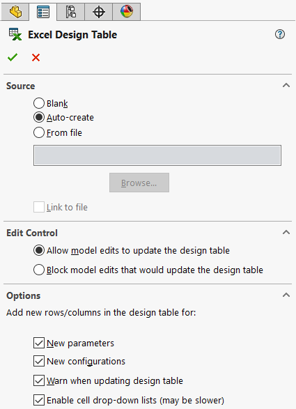
Excel Design Table options in SOLIDWORKS
The auto-create option is the most used source. This prompts you to select which dimensions and features you want to control and automatically creates the table with the correct format and syntax for you. This will also automatically populate the table for any configurations and configured parameters that already have been specified. Because of the syntax involved, it may not always be obvious what the parameter names or values should be. So, it is common for people to start configuring a model manually, to establish which parameters need to be configured, then auto-create a design table so that they can then paste in the values for their configurations.
With the blank option, SOLIDWORKS will also recognize configurations and configured parameters and will offer to add them through a dialog where you can pick which configurations to create as rows and which parameters to create as columns.
The from file option assumes that you know the parameter syntax and the spreadsheet is formatted correctly. In most cases, these files come from other configured parts. The design table is saved (by right-selecting the design table from the tables folder in the configuration manager) or the design table is opened (by choosing Edit Table in the same right-select menu) and the data is copied and pasted into a new Excel document. Then the data is modified as needed, and the file is brought into another SOLIDWORKS model to configure the new model.
Once a design table has been created, it can be expanded. While the design table is being edited, you can double-click on features and parameters within the model, and columns will be added to the design table for the suppression state of that feature or the value of the selected dimension.
Syntax exists for other parameters like custom properties, feature parameters like scale feature parameters, and configuration parameters, like color. The details on most of these syntaxes are documented in the SOLIDWORKS help, but some (like the scale feature) are best added through the auto-create or double-click during table edit methods.
It is important to note that there are some particularities in the formatting and structure of the design table. The parameter names must be in row two, and the configuration names must start in row three. Cell A1 must always be blank. You must also be sure not to leave any blank rows. Once SOLIDWORKS encounters an empty configuration name in the first column, it will assume the bottom of the table has been reached.
Creating SOLIDWORKS configurations with the configuration publisher
Quite a few years ago, SOLIDWORKS developed the concept that became 3DContentCentral. The general idea was to provide a way for SOLIDWORKS users to market their products by making them available to other SOLIDWORKS users inside of SOLIDWORKS. The theory was that the convenience of being able to pull SOLIDWORKS models straight from a catalog and drop them directly into your SOLIDWORKS assemblies would provide unmatched convenience, making your products more attractive.
To facilitate the creation of product families to promote in 3DContentCentral, SOLIDWORKS introduced the Configuration Publisher. This tool allows you to create a more user-focused interface to create configurations of your models. With typical methods, when you select a configuration to use, you are simply pouring through a list of configuration names. The configuration publisher allows you to create a custom property manager where users can specify the inputs to drive the configurable model, rather than selecting from a list of predefined configurations. This means that your users do not need to know the names of your configurations.
Using the configuration publisher begins with a configurable model with a design table. If you want to predefine all of your configurations, ensuring that your users can only select from approved design configurations, then add the rows to your design table to define the configurations. SOLIDWORKS refers to this as the multiple configuration method because you are determining the allowable configurations for your product.
Launching the configuration publisher (from a right-select at the top of the feature manager or configuration manager) will present you with a pulldown or checkbox for each column in your design table. You can drag these controls into the design area to create your custom PropertyManager. You can change the label on the input to create a slightly better user experience. Visibility conditions can also be applied where the visibility of a control is based upon the value of another control (you specify the “parent” control and a hide/show value for each value of the parent).
Additionally, the configuration publisher can be used to control configurable models that do not have all the configurations predefined (known as the single-configuration method). This method still requires a design table, to determine what parameters about the model can be controlled. With this approach, SOLIDWORKS provides not only list and checkbox controls, but also number fields that allow your users to enter any number.
Choosing the most suitable method
Whether you use the manual, configuration table (modify configurations dialog), or the design table method generally depends on where you are in your design process, how many configurations and parameters you must populate, and the source of your data.
These methods are all perfectly valid whether you’re creating a part model or an assembly model. Manual, configuration tables, and design tables all support both parts and assemblies.
The methods are not mutually exclusive, either. Manual changes can be made to update design tables (a setting in the design table properties) and will automatically update in the Modify Configurations dialog. Most models are commonly created with a few configurations, to test out the parameter changes, and to capture the parameters as being configurable. Then, once all the features and parameters are defined and tuned, the data is populated in a design table to create all the configurations.
Using SOLIDWORKS Configurations
At the start of this article, we identified three primary use cases for SOLIDWORKS configurations.
- Creating configurations for “same, but different” products which have different sizes or options allows us to quickly create similar models and store them together in a single file.
- Representing the model in different states, for example, a moving component that could have an open configuration and a closed configuration, or a product that might exist in different states through a process like manufacturing.
- Streamlining downstream processes, for example, creating a simplified model for graphical or performance reasons, a model optimized for simulation or CAM, or a version of the model that has been modified for some reason, such as to demonstrate maintenance processes.
When it comes to utilizing configured models to create further parts and assemblies, the simplicity lies in the fact that you really only get to change which configuration is being used. When a configured part is being used as a base part, for example, the base part feature has the ability to select which configuration is used as the base part. This allows us to create a cast part and save configurations representing the different sizes of that cast part, then use the base part feature to insert the casting into a new part. We can then select which size casting we are using, then add our manufacturing steps as features to machine the cast part. Using the base part functionality, in this case, allows us to keep the cast part as a separate file to segregate our intellectual property or to allow us to use the same casting to create multiple products, machining each one differently. Similar functionality is available for split parts.
Using part configurations in assemblies
The use of configurations can certainly reduce the number of SOLIDWORKS files in your library. When you can store dozens or even hundreds of washers in a single washer.sldprt file, it will definitely reduce the number of files in your hardware library folder, making it easier to know which model to insert into your assembly. Let’s take a look at the mechanisms for specifying and managing your component configurations inside of a SOLIDWORKS assembly.
Note that the term component refers to something that is inserted into an assembly. Components can be parts or they can be assemblies inserted into a larger assembly. Subassembly components act like parts in the way that they contain configurations to represent multiple versions but act like assemblies in the ways that they consume the parts that compose them. This is why we’ve been very careful to refer to models in the previous articles, and not specify parts or assemblies, except when there was a unique reason.
Configured components are inserted into your SOLIDWORKS assemblies the same way that any other component would be. In most cases, you may not even know that the component that you just inserted has configurations. In fact, every model starts with a configuration called “Default”, and there is no indication in the Feature Manager whether your component has more configurations.
The same three methods for creating and managing your configurations discussed in the last article are also available to manage the configurations of components in an assembly. When it comes to assemblies, the parameters that we control fall into three categories. The first is the control of the individual instances of the components inserted into your assembly. These parameters include:
- Suppression state of each component instance
- Referenced configuration of each component instance
- Fix or float component positioning for each component instance
- The display state of the component (we’ll discuss this in a later article)
The second category provides controls for features in the assembly. These could be assembly features in the classic sense, like cuts and holes, but also refers to mates, sketches, patterns, reference geometry, and other features that can be added to assemblies.
- Suppression state of each feature
- Suppression state of sketch relations
- End conditions and other feature parameters, where appropriate
- Dimension values associated with the feature
- Hole wizard sizes
The final category adds control for the properties of the assembly itself. This includes:
- Configuration-specific custom properties
- Properties of the configurations themselves, like color, part number, and description
- Mass properties (when overriding the calculated mass and center of gravity values)
Creating configurations in assemblies
Creating configurations in the assemblies themselves once again returns us to the use cases. If the assembly is a “same, but different” product, then assembly configurations can be used to control the configurations of the parts that make up the product by configuring the component instance configuration being referenced.
It is also very common to insert two different parts into the assembly and use the suppression states to determine which component is being used in each configuration. Doing this will inevitably require controlling the suppression of mates for each configuration. Because SOLIDWORKS does not provide any functionality for configurations to replace components, the introduction of these mutually exclusive or competing components is the most common solution. Similarly, without the ability to configure the references in your mates, the most common solution is to create mates that are specific to a component and control their suppress state to match that of the component that they mate.
To address the use case where an assembly may exist in multiple states, component suppression is frequently used to remove components for illustrative or analysis purposes. One aspect to consider, however, is that component suppression removes the component from mate-solving calculations. It removes the references for the suppressed component. This can lead to problems with child features, like mates, reference and assembly features, and even annotations and reference dimensions being deleted or dangling. Components can be hidden in assemblies, rather than suppressed, which means that they are still present in the calculations and will prevent the dangling issues. The visibility state for components, however, cannot be configured.
We will discuss a functionality called display states in a later article in this series, as a solution to this problem.
There may be a temptation to view the use case for configurations to simplify, as we discussed for analysis or CAM, and to apply that to an assembly for performance reasons. As assemblies grow, performance may degrade to the point where assemblies can become unusable on lower-powered workstations. While configurations may seem like an opportunity to create more simplified versions that will load faster, SOLIDWORKS does provide a series of Large Assembly tools to help with these performance issues. These tools generally focus on loading lightweight versions of the models or not loading parts based on criteria like volume. These methods will generally be sufficient until you need to access references on these parts. The developers at SOLIDWORKS have implemented these Large Assembly Mode tools to allow you to automate the loading of the full part only when you need those details.
The preferred process for creating assembly configurations is primary manual creation. This is due mostly to the workflow for how assemblies are created. Users generally find it easier to handle the configurability for a component as they add it to the assembly. The flow becomes:
Insert Component(s) > Select Component Configuration > Mate > Save > Repeat
When it comes to creating assemblies with configurations that have competing or mutually exclusive components, the workflow is typically the same, but you just need to make sure that you activate the correct assembly configuration first. As with the manual process in part modeling, you are making changes to update the active configuration. There are similar tools to automatically suppress new features and mates and automatically suppress new components that are added when a configuration is not active. Prudent use of these options can save a lot of time.
Two additional functionalities that do not necessarily require assembly configurations, yet are implemented as a part of configurations is the creation of assembly exploded and break views. Exploded views are an assembly functionality, and not a drawing functionality, while drawings do have the ability to break a view, the assembly functionality is a bit more powerful. It is important to note that the exploded views must be created in the assembly and exploded views and break views actually belong to a configuration.
Designing for change
The basic principle is that your model must be able to change to create all the configurations create without any errors.
That shouldn’t be a problem because SOLIDWORKS is all about change. But to make things more difficult, you can only use the tools available to configurations to make these changes. That means that you can change the suppression state of features, dimension values, and other parameters. But it also means that you cannot change a sketch rectangle into a sketch circle. And it means that you cannot edit the definition of your chamfer and change it from angle-distance to distance-distance. And it means that you can’t change that hole wizard hole from a countersunk hole to a slot.
This does not mean that you need to abandon configurations altogether. It just means that you need to plan and make sure that your models are designed for configurability. This may go against some of the guidelines that you learned in training. It may go against the “every feature should correspond directly, one-to-one, with a manufacturing step to be performed out on the shop floor” approach that you try to adopt.
The important thing to realize is that we’re going to expect SOLIDWORKS to make changes to our model, rebuild and present the result. As any SOLIDWORKS user knows, making changes can cause problems. Sometimes references are lost or bad geometric conditions are encountered. If this situation occurs during your daily life of making manual changes in SOLIDWORKS, it’s not a huge deal. You’ll get the What’s Wrong dialog, and you can go in and address the issue by editing features or sketches and selecting new references or adding new relations or dimensions.
When you use Configurations, you don’t get the same visibility and feedback. You are going to be in a completely different context (in a drawing or in an assembly) and you’re going to invoke all these changes (feature suppressions, dimensional values, etc.) remotely by simply picking a new configuration to use. After making the changes, SOLIDWORKS is going to silently rebuild the model in the background. You must be sure that the model will rebuild properly.
This means planning, testing, and applying some basic best practices.
Design Intent
Probably the most important aspect of a configurable model lies in the model’s representation of your design intent. Design intent is all the knowledge and rules that determine why your model looks the way that it does, and more importantly, ensures that it will respond correctly to change. The tools that you use to establish your sketches and your features, and your bodies and your assemblies determine how your design will react to changes.
When you add a sketch relation, for example, making two holes equal, you are not just saying that they just happen to have the same value for their diameter. You are establishing a rule, a parametric equation in a series of equations that SOLIDWORKS uses to solve your sketch, that says that these two circles must have the same diameter…always. If this is not the intention of your design, then you should reconsider this relation, and add two separate dimensions instead. By having two separate dimensions, you have the flexibility to set the diameters for those circles independently.
And this concept extends beyond sketch relations into dimensioning schemes, the features that you choose, the references and end conditions that you select, mating systems, and many other aspects of how you build your model. As you design your model, you need to constantly plan, considering what can change, what can/will be driven in your configurations, and how those changes will affect the feature that you’re currently creating.
It’s a great idea to document your planning so that you or another member of your team can refer to how your models have been setup.
When you select multiple edges in a fillet or chamfer or add multiple points to a hole wizard sketch, you are establishing a relationship that will always be processed together. If you need to suppress or drive them individually, make sure that you build them as separate features.
Similarly, when you choose a face or plane to sketch on, consider whether anything further up in the Feature Manager tree could affect this face or plane. Will changing a dimension move this face or plane? Will suppressing an earlier feature cause this face or plane to no longer exist or be changed? And if any of these conditions exist, consider the question are you selecting this face or plane because that is the intent of the design, or because that face or plane just happens to be in the correct spot with the current set of values and options?
Configurable model best practices
One core practice that should be a requirement for configurable modeling is the naming of all parameters to be driven by configurations. Once you get into a configuration or design table, the only way to know what you are driving with your configuration is by the name. This means the name of the feature or sketch and the names of any dimensions you plan to drive. Take a moment to give them a meaningful and unique name. Keep in mind that dimensions will be in the context of their sketch or feature, so when we say that the names need to be unique, “ID” is a perfectly good name for an inner diameter if you name the sketch or feature to which it belongs. Once you get into your table, you will be able to see “ID@TopBoltHole” and “ID@skFlange” as the full name. “ID@Sketch5”, however, will be difficult to identify and manage.
Another core practice that you can develop when creating configurable models, is to always be aware of the relationships that you are establishing. When you create an extrusion, you automatically create some parent-child relationships between not only the sketch and the feature but also between the sketch and the face or plane that you selected as your sketch plane. End conditions can create parent-child relationships. The edges and faces that you select as references for features like fillets and shells and edge flanges all create parent-child relationships.
The issue with parent-child relationships is that when a parent is suppressed (remember that we’re creating a model that changes), you have to make sure that everything downstream (i.e. below in the Feature Manager) will still have all of the references that they need to recalculate properly. This is where the planning comes into the picture. If you understand, while you’re building your model, what features are going to be suppressed in some configurations, then you can make sure that all downstream features reference entities that will persist through your configurations.
The key is to pay attention to the steps that you use to create your features through the lens of creating dynamic, configurable models, in order to avoid any unwanted parent-child relations. Understand what entities are going to be suppressed, and which will persist. Here are some tips to help you avoid unwanted parent-child relations:
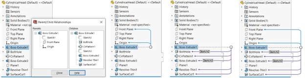
View parent and child relations for features in SOLIDWORKS
- Check your parent-child relations on any feature that will be suppressed. You can right-select any feature and choose Parent/Child to view the relations in both directions. You can also right-select the top-level model in the tree and enable Dynamic Reference Visualization, which will show arrows to the parents and/or the child features as you select any feature in the Feature Manager. Remember that sketches are features, too, and have their own parent-child relations, as do other sub-features.
- When looking to find your parent-child relations, always start at the sub-features. In sketches, look at your sketch plane reference, dimension references, and geometric relations (use the Display/Delete Relations tool). For features, use the Edit Feature property manager and look for any selection that could potentially create a relationship (ex. end conditions, pattern references, selected entities).
- Whenever possible, use the origin and default datum planes. These references are universal across parts and are guaranteed to persist, as they occupy the top spot in the Feature Manager.
- When you can’t use the default datum planes, consider creating other reference geometry (planes, axes, sketches, points, etc.) that can still represent your design intent, while creating entities that will persist. Remember that creating these entities can also create parent-child relationships, so consider creating the references first, and reference them multiple times.
- Reference geometry should still be created to represent your design intent. Ensure that the dimensions that you use to define your reference geometry are the same dimensions that you would be using for inspection or machining.
- Faces are subject to “destruction” by downstream features. When a face is split or trimmed or otherwise modified by intersecting with a new feature, it may lose its original internal identifier, causing SOLIDWORKS to no longer recognize it as the same face.
- Don’t ignore grandchild and greatgrandchild relationships as well. These indirect relationships can also be problematic when any predecessor is removed or modified.
- Mates are also subject to Parent/Child relations. When configuring assemblies, ensure that your mate references will persist between configurations. Consider mating to reference geometry when appropriate.
Configurable solving of sketches and mates
When it comes to the hot list of areas within these configurable models that cause problems, right behind parent/child relations are sketches and mates. We’ve already identified the top issue with sketches and mates, which happens to be parent/child relationships that go dangly.
The second complication with both of these technologies lies in the fact that they both use a parametric solver to combine a series of relations into a singular geometric state. We see two behaviors with parametric solvers that can be a bit unpredictable at times. The first has to do with making large changes. When a value changes from one inch to 500 inches, it is more likely to cause unpredictable results than if it simply changes from one inch to two inches. Geometry and dimensions may flip. Arcs may invert. Strange things can happen. Is the resultant geometry a valid solution to the set of constraints that you have specified? Probably. Is it something manufacturable? Quite often not.
These types of unpredictable behaviors can often be avoided by simplifying your sketches into a smaller number of entities and relations. This often requires you to create multiple features, in order to create a more stable model. This is not a problem. It just means that you will need to add a few more columns to your design table. You can even group the features together into a feature folder and drive it with a single column, if that really bothers you.
The other source of unpredictability lies in the use of relations with multiple solutions. Relations like tangency often have many valid solutions. Even dimensions (typically between sketch entities or in distance mates) can often change directions while still providing a valid solution. In some cases, intelligent choice of a reference (typically the one outside of the sketch or in the static portion of the assembly, the “grounding reference”, if you will) can provide a more stable sketch or mate solution. Most often, simplifying the sketch will be the best way to solve this problem as well.
Another misstep to avoid with dimensions in sketches, features and mates is to never use negative values. SOLIDWORKS allows for the use of negative values in some situations. The dimension itself is not negative, but it tells SOLIDWORKS to flip the dimension, and then apply the value. That’s fine if you know the existing state of the model. But in an “automated” world where we are doing all of this blindfolded, the negative values just don’t work. Spend a moment to establish a reference where you can be assured that you will have a positive value, setting up a second feature or second mate if you have to.
Never underestimate the importance of testing
Manual creation of your configurations actually builds some level of testing into the creation of your model. As you switch between configurations, you are testing out the changes that you are capturing. It is very important to test your model constantly, and thoroughly throughout the creation process. Configuration tables and design tables can push a lot of changes at once. Make sure that you click through your configurations checking not only that they do not have errors, but also that they are being driven properly to the correct dimensions, with the correct features suppress, and with the correct property and parameter values.
As mentioned above, the most common problems occur when large changes are made, so as you create features that will have to change, manually enter the values that your configurations will be pushing into the dimensions. Test the values at the extremes to ensure that when you change from your smallest configuration to your largest, no problems occur. Change multiple dimensions at once. Going through each dimension might not cause problems, but remember that your configuration will be making all of these changes at once.
The more elaborate your configurable model, and the more configurations you are creating, the more time will be required for testing. Be sure to plan for this time, and ensure that you have an intelligent way to validate your model’s configurations. Know what you need to look for in each of your configurations to determine if the configuration generated successfully.
The key to creating stable, usable configurations is planning. That doesn’t mean that you have to sit down and develop specification documentation before you start modeling. But it does mean that you should always plan ahead for which features you will control, and ensure that any references that you make will persist as your model changes. Understand what will change, and make sure that you plan for that change.
Advanced techniques
At DriveWorks, we’re leaders in automating SOLIDWORKS. And while there’s a lot that DriveWorks can do with SOLIDWORKS models that you cannot do with standard SOLIDWORKS functionality, there are techniques that we utilize that can be applied to standard SOLIDWORKS configurations.
In this section, we’re going to look at some of those techniques to help you create more powerful and flexible SOLIDWORKS Configurations.
Using reference geometry
Reference geometry can be utilized to create more stable models and to overcome issues that may be encountered due to parent-child relationships. Reference geometry can be used in many other ways, as well, to create models that are more configurable and intelligent. The key is to leverage reference geometry to represent your design intent more accurately
For example, centrelines in sketches can be used in conjunction with an equal relationship to represent a consistent wall thickness in cases where an offset relationship or a shell feature are not feasible. Here, the design intent on the left says that there are several areas that should all be 0.25 thick. But if the design intent is that they should all be equal, then the use of sketch centrelines and equal relations shown on the right will ensure that those thicknesses are always identical and that you only need to drive a single dimension.
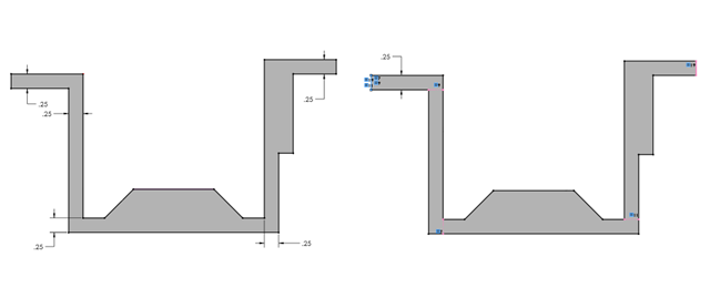
Example use of SOLIDWORKS Reference Geometry
The limitation of sketch relations is that they are designed to be solved within a single sketch. However, if you have edges in different features that need to be related, you can show a sketch and set relations between entities in different sketches, if they are on parallel planes.
Link values, equations, and global variables
For situations where you have geometry in non-parallel planes, there are a variety of additional techniques that you can use. The link values functionality allows you to create two dimensions that are tied to share a value. In typical situations, link values allow you to change any linked dimension and all of the dimensions will update. For our interests, we will always be driving the same dimension, but this is a quick and easy way to tie dimensions together.
Essentially, all link values does is create an equation between dimensions and a global variable. Both techniques, equations and global variables, are excellent tools for working with configured models. There is a goal with configured models to drive as few parameters as possible. But this is not a matter of efficiency, this comes down to design intent. In most cases where we see SOLIDWORKS users driving too many parameters in their design tables or configured models, it’s because they’re not approaching their driven parameters from the viewpoint of customer inputs.
If you think about your design tables as documenting the choices that you are asking your customers to make (imagine the Configuration Publisher with a field for each customer input), when you have multiple columns in your design table with the same value, you must rely on the customer to know that the thickness of these different features should be the same. That’s design intent, that’s not something that you should be relying on your customers to know or do. If those two thicknesses should always be the same, then there should be a single column in the design table for “wall thickness” and all the relevant thicknesses should be driven from that.
Link values is one method to do this. Equations and global variables are another great method to do this. Your design table can drive the value of a global variable. That global variable can, in turn, be used to drive geometry and even custom properties to populate your bill of materials and drawing annotations.
Any design intent rules that determine values (for example, when the thickness of your part is determined by the provisions of UG-16 of Section VIII of the 2022 ASME Boiler and Pressure Vessel code), then that design intent deserves to be built into your model just as much as a horizontal sketch relation. Equations and global variables allow you to include these calculations. Global variables even allow you to use your design table to add inputs that you would not be able to input otherwise. What type of sketch dimension would allow you to enter the internal pressure of your pressure vessel? Defining the internal pressure for your pressure vessel in the design table would allow you to calculate the wall thickness with an equation.
Leveraging Excel in your design tables
When creating many configurations, you can utilize the fill and autocomplete functionalities within the Excel interface. In fact, it is very common to export or copy the design table out into an external spreadsheet, so that it can be developed into the completed table. This is the primary reason for the “From file” option in the Insert Design Table property manager.
However, it is very easy to forget that the formulas exist when adding a row to your design table. In this case, the design intent will be lost in the new row. The formulas that you captured will not be applied across all the configurations. You can try adding comments, formatting, etc. to try to notify whichever user is accessing the design table that formulas exist, but this becomes a maintenance issue.
Additionally, when you split your design intent between the SOLIDWORKS model itself and the design table, you lose the ability to create custom configurations by editing the SOLIDWORKS model. If you create all your predetermined configurations using formulas in the design table, if you try to add a new configuration manually, the values will not include any of the rules that you built into the design table.
Consolidating driven values with layout sketches
The last technique that we want to review is the use of layout sketches. A layout sketch is any 2D or 3D sketch that is used to drive multiple downstream features. Some models lend themselves very well to this technique, and others, not as much.
The layouts allow you to put all of your driving dimensions in sketches at the top of the tree. This allows you to have all of your sketch entities in a single sketch, making it easier to apply reference geometry and relations to represent your design intent. This also allows you to put everything into the model, right at the top of the tree, which can alleviate a large number of headaches caused by parent-child dependencies.
SOLIDWORKS provides a large number of tools for capturing your model’s design intent. The important point is to ensure that your model’s design intent is captured completely and properly. Design intent controls not only how your model is shaped, but why it is shaped that way, and how it reacts to change. By controlling the change, we can input the values that our customers will know, and determine the dimensions that our model actually needs.
Considerations and challenges
Performance
Configurations provide the functionality to reduce the number of mouse clicks that it takes you to insert a new component into an assembly or create a family of “same, but different” parts, or create multiple drawings of a part in a variety of its states of being. The first downside that we see is due to the fact that when we consume a single M5-0.8 x 25mm socket head cap screw, we are not just inserting that one screw, but instead, we are inserting the entire family of screws.
The concept of the configurable part is that we are typically defining an entire family of parts inside of a single part file. Our SOLIDWORKS assembly must be able to display the geometry for the active configuration, and the feature manager for the active configuration, and potentially display multiple configurations of the same part as different instances in the same assembly (I mean, the Ikea cabinet that I just built had nine sizes of screws in it!). This means that the part file must contain a considerable amount of information about each and every configuration and/or calculate that information for every configuration as required.
The first thing that you will notice about parts with a lot of configurations is that the file size can get pretty big. As mentioned above, there is geometric information, preview information, feature manager information, and other information about every single configuration, plus there’s Excel file information for your design table and other configuration-specific information that you would not normally have in a model file for a single part. Large file sizes can lead to long loading times, especially when the assembly is being loaded over a network. Additionally, when you do a pack and go, or use some other method to move or copy your assembly, you’re not just transporting one or two screws, you have to include the entire library, every time that you want to transport that assembly.
There are other performance considerations with configured parts as well, namely all of the extraneous features that are included in the configurable model that are suppressed for the current configuration. This is a massive consideration when developing your configurable components. Can we have one part called screw.sldprt that includes every size screw with every type of head and every type of point and every type of thread and shoulders and eyes and hooks and U’s and J’s and a second thread (to include hanger bolts)? Yes, we certainly can. But just because we can, that doesn’t mean that we should.
The benefit from creating families of parts is that we can quickly create the parts, and that we can easily switch between them in an assembly. Once we have configuration lists that are too long to easily scroll, and parts that take too long to load, and cannot be easily transported or loaded over a network, we lose the speed benefit. The time that we saved by creating the design table is lost every time that we wait for the assembly to load. This is a classic balancing act. We can leverage the power of configurations to create a reasonable number of parts within a single file. We can reduce a library full of hardware into a reasonable number of part files, instead of trying to cram it all into one monstrously huge file.
Maintainability
SOLIDWORKS models that contain configurations are more complicated than a standard models. When something is complicated, that typically means that it has a lot of (literal or figurative) moving parts. And when it comes to configurable models, the parts start moving when you make changes.
When a change is made to any configuration, that change is being made in all configurations, unless you pay careful attention to ensure that the other configurations are not affected…unless you want them to be affected. This is where the design intent becomes crucial. We talked about design intent in previous articles in this series, as representing why your model looks the way that it does and controlling how your model reacts to change. We are, after all, designing these models to change within the parameters of the configurations. But when the time comes to change that design intent (and this is engineering design, that time will come), the implications of how design intent is changed must be considered carefully.
The typical nightmare scenario that we see comes in the form of an organization with a few SOLIDWORKS power users that create complicated configuration-based models, only to have more basic users consume those models and make innocent changes “just for their application”. It is very easy to have a change that is only meant for a single configuration inadvertently affect a large number of other configurations. Those configurations, in turn, can cause problems in every assembly and drawing where they are used. And due to the way that the models are configured, it’s possible that the user causing the change will not have any idea of the impact of their change, and who will be affected.
Configurations and data management
I can hear you right now, “Well, that can’t happen to me, I have PDM!” Having spent the last 25 years in the PDM/PLM market space, I can tell you quite definitively that there is no concept in all of Computer Aided Engineering Design that causes more complications and problems in PDM and PLM than configurations.
Let’s think about the basic PDM premise. Product Data Management means that I want to manage the product’s data, that’s the files. We need some power to be able to search and manage data, so we get a database involved. It seems pretty straightforward at first, you have a database record representing a part, and you link it to the file. Well, what happens when the same file now corresponds to a series of parts? Do you have one database record for the one file? Do you have one database record for each configuration in the file? What about when a change is made, do you revise every part that is in that file because the file was revised? Do you manage the revision of each configuration independently? Is that even possible?
The answer to all of these questions, of course, is “it depends”. Remember that there are a variety of use cases for configurations. If you have a family of parts, then you would certainly want a different object for each configuration. But if you create configurations for the open and closed positions of a hinge, that should only be a single object in the database.
There are a variety of ways that PDM and PLM solutions have evolved to deal with this CAD file-Object conundrum. But since configurations can be used differently by every organization (and often used in different ways within the same organization), the solution is often customized or personalized in some way, and rarely simple.
While creating configurations can seem like a fast way to create a large number of parts, the overhead associated with carrying those parts around inside of a single part file can cause performance problems when opening, working with and transporting assemblies.
Care should be taken when planning your part families to ensure that you are not overloading your part files so much that you will lose the time that you saved in creating them when you use them.
Additionally, having multiple parts within a single file can significantly complicate the process of making changes to the file, as a change to a single configuration can easily (an unknowingly) affect other configurations. This could, in turn, affect assemblies that use those configurations.
Data management tasks become equally complicated by the concept of having multiple items within a single file (and sometimes having configurations representing the same item). How configurations are going to be utilized will have to be considered carefully when planning how to implement PDM and PLM systems.
Alternatives to configurations in SOLIDWORKS
Controlling assembly display with display states
While our example use case involves leveraging configurations to view models (parts or assemblies) in different stages of a process, SOLIDWORKS does provide functionality to allow you to control the display of components in an assembly. Display States are actually tied to a configuration, and appear at the bottom of the Configuration Manager. There is a distinct difference between configurations and display states in that configurations can control the geometry of the model (i.e. things that need to be solved, like dimension parametrics, sketches, and mating schemes), while display states are designed to control the visual properties of components within an assembly (ex. hide/show, color, transparency).
But even with this smaller set of tools, this functionality will still allow us to satisfy the use case where we are creating different configurations of an assembly so that we can create different assembly drawing views showing the various assembly steps of the product. Once we get into a drawing, each drawing view can specify not only which configuration is being displayed in the drawing view, but also which display state.
It is important to note that display states can be used to control the visibility of components within an assembly or the visibility of solid bodies within a part model. This means that weldments, mold/castings, and other examples of multibody solid modeling within a part can take advantage of the display state functionality just as well as an assembly model.
Configurable models without the configurations
The majority of this article focused on creating stable models that react reliably and predictably to change and capturing the design intent behind our product, not just the geometry. These are sound SOLIDWORKS modeling practices, even if you don’t plan on creating configurable models. But the techniques with layout, equations, and global variables were designed to help us create models where all of the design inputs were easily accessible.
Previously, we leveraged that accessibility to make configurations of our product, but we could just as easily make multiple models, using that geometry as a template. One concern with configurations is the concept of having to carry along an entire product line, when our interest really lies in only one product. The most common solution to this situation is to simply use the File, Save As to create a unique model. This has the advantage that it creates a separate file with no links back to the original. That means that if anyone makes changes to the original file, our copy is safe, a true record of how this particular product was produced, and “as shipped” record.
We can then, easily archive this file in the customer’s folder, and zip it up nicely in a pack and go of the assembly, as it will only contain the single product of our interest. We still get to leverage the configurability built into our original file because once we perform our Save As, we simply drive the values of our inputs. This could be a single line in a design table. This could be with our Configuration Publisher. This could be by entering values into global variables in the equation editor. Or this could be by simply bringing up our layout sketch and driving the values there.
By taking the time to create a configurable model, we can very quickly and easily create different versions of our product as separate files.
Using the SOLIDWORKS API
Repetitive tasks, like creating a large number of “same but different” models, lend themselves to programming. And SOLIDWORKS does include access to the SOLIDWORKS Application Programmer Interface (API) with every seat of SOLIDWORKS. Through the macro menu, you can easily start the macro recorder, perform a Save As, change all of the values in your model, rebuild the model, then save the model, and when you press Stop on the macro recorder, you will have all of the code that you need to create a new variant of your product. A quick internet search for something like “Automating SOLIDWORKS with Excel” (or whatever your interest is) should reveal no shortage of SOLIDWORKS API samples and presentations and articles and videos on how to very quickly utilize the SOLIDWORKS API to automate the creation of models. So, if you have tables of different variants of your product, you can have your API program read the data from those tables and create all of the models for you.
You can learn more in our guide on automating SOLIDWORKS using the API and macros.
Automate SOLIDWORKS without the hassle
DriveWorksXpress is included for free inside SOLIDWORKS and gives you access to powerful design automation tools.
DriveWorksXpress is what the configuration publisher dreams that it could be, a place where you can create forms to collect your inputs, and (unlike the configuration publisher, which just passes the values to a design table) DriveWorksXpress allows you to write rules to convert those inputs into values that drive dimensions, feature suppression, custom properties, and other advanced feature properties.
DriveWorksXpress replaces the need to use SOLIDWORKS equations and instead provides a much more robust set of functions to calculate your values.
Setting up DriveWorksXpress is quick and easy:
- Capture and control the parameters you manually change in your SOLIDWORKS models and assemblies in DriveWorksXpress
- Create input forms to enter product requirements. Add validation to controls to ensure inputs are always suitable
- Build rules to link input controls with captured parameters using the intelligent DriveWorks rules builder
Once you have DriveWorksXpress set up, you can automatically create custom SOLIDWORKS data again and again. DriveWorks will duplicate and update your SOLIDWORKS files using the product requirements you enter. DriveWorks is flexible and scalable too, so if you get started for free with DriveWorksXpress, you can migrate your project to take advantage of more features in DriveWorks Solo or DriveWorks Pro when you’re ready.